Sour Water Stripping Unit
Sour Water Process flow
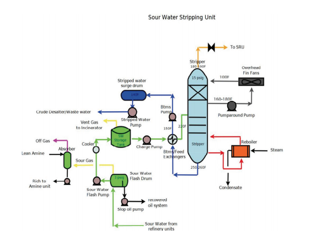
 Sour Water is typically routed to the Sour Water Unit through a main Header that individual units such as Crude, Reformer, Diesel etc. tie into. As it enters the unit it is sent through the Sour Water Flashdrum, where entrained hydrocarbons are separated from the water. Light hydrocarbon is flashed off and sent to an absorber, heavier hydrocarbon is pumped to a slop tank or Blowdown, and the Sour water is then routed to a Sour Water Storage tank. From the Sour Water Storage tank the water is pumped to feed/bottom exchangers and then to the Stripper itself. A reboiler supplies Stripper drive and helps control tower heat balance. Fin Fans/coolers control overhead temperature, with the overhead gas being sent to the Claus unit. Stripper bottoms typically is routed to a Crude Desalter via a Stripped Water Surge Drum with excess typically sent to the Waste Water Unit.
Basic Chemistry
As previously mentioned, Steam Stripping is the most common and simplest method for removing contaminants. Two major contaminants are H2S and NH3. Both of these are soluble in water. But Refinery sour water contains a host of contaminants that affect the equilibrium of the process. Contaminants that are Acidic , such as chlorides, cyanides and phenols, lower the pH and tend to prevent ammonia from being stripped but free up the sulfides. While Alkaline contaminants raise the pH, improve ammonia stripping, but tie up the sulfides. Hydrocarbons can be entrained and as they are liberated, foul the Stripper Trays.
To add to the complexity of stripping sour water, the make up constantly changes through different crude slates that are being processed. In the Sour Water H2S and NH3 are present as NH4HS, which is a salt of a weak base and a weak acid. Weak acid being represented H2S and NH3 being the weak base . NH4 is the Ammonium ion and HS is the hydrogen sulfide ion represented in solution. The equilibrium is affected by temperature, raising the temperature shifts the process to dissociating the salt and freeing the gases.
A walk through the unit; pipe, process and equipment
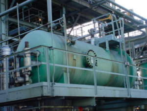 Sour Water Flash Drum: As Sour Water streams are routed into the Sour Water Unit, they are fed into a main header and to the Sour Water Flash Drum where hydrocarbons are separated from the water. A baffle near one end of the flashdrum skims oil from the Sour Water before it is pumped to the Sour Water Tank. The recovered oil overflows a weir at the other end of the flashdrum and is pumped to some type of recovered oil tank or process. The Flash drum pressure is set low so as to “flash” off light hydrocarbon. Instrumentation for the Flash Drum would included Sight Glasses for both oil and water side, Level alarms Hi/Low and Pressure Indication.
Sour Water Flash Drum Pump: Typically has a spare with an auto-start. It takes suction on the Drum and routes feed to Sour Water Storage Tank.
Sour Water Flash Drum Oil Pump: Since build up of the oil level in the flash drum is not always constant, this pump is usually run on an auto start controlled by level on the oil side. Oil is routed to the recovered oil system.
Sour Water Storage Tank: The Sour Water Tank takes incoming feed from Refinery sources. Dependent on the source temperature, a cooler, typically a plate cooler will decrease feed temperature and prevent building vapor pressure in the tank. It is advisable to have some storage capacity in the tank to account for any issues that may occur in the Sour Water Stripping Unit. Also more residence time supports better separation of water and oil and allows the refiner to skim the oil pad from the tank through attaching tank nozzles routed to a skim pump. The oil can be skimmed off through a floating Skim nozzle or by Operations raising or lowering the level in the tank to access the oil pad for skimming.
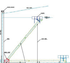 The included illustration provides a view of a floating suction line for a tank. In a Sour Water Tank, the Oil pad would rise to the top and the nozzle will take suction at the pad.
The tank roof itself can be a cone roof, which is very common as it is a lower cost or a
floating roof that will avoid an explosive mixture problem, but will have issues around odor. If the tank has a cone roof, then it will have to be protected by Pressure Relief Valves and Vacuum breakers. The PSV’s will protect the tank from over pressuring and the Vacuum breaker will allow air into the tank to prevent collapsing the tank. This situation could result in a explosive mixture of fue/H2S and Oxygen. Because of this, Cone Roofs have a N2 or Gas Blanketing to protect from implosion. Instrumentation on the Sour Water Storage Tank is dependent on whether it is a floating roof or cone roof. Both will need Level and pressure indication and sample draws The cone roof tank instrumentation will include blanket gas pressure controllers. Vent gas is normally routed to incinerator.
Skim Oil Pump: Takes suction off the Sour Water Storage tank at oil pad and pumps oil to recovered oil tank or system.
Sour Water Charge Pump: Takes suction off the Sour Water Storage tank and pumps Sour Water feed to the Feed/Bottom exchangers. This pump will usually have a spare with an auto start. Depending on where the tank is located there might also be additional booster pumps closer to the unit to supply feed to the tower.
Feed/Bottom Exchanger: The sour water feed/bottom exchangers serve a dual purpose. It heats the Sour Water Feed on the tube side and cools the outgoing Stripper bottoms. Feed entering the Stripper from the exchanger runs in the range of 170-220°F, with the outgoing Stripper bottoms on the Shell side running from 150-170°F on the outlet of the exchanger. Instrumentation for the exchangers include inlet and outlet Temperature indication. The temperature profile for the exchangers is telling, as it is a leading indicator whether the exchangers are fouling. As they become “dirty” they will lose heat transfer ability.
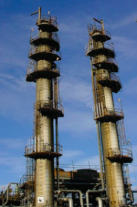
Sour Water Stripper: A typical Stripper tower is relatively tall and narrow containing several trays. It includes a pump around draw tray with chimney risers and a packed section. The Trays and packed section provide for good liquid/vapor contact where contaminants are stripped from the sour water. Trays are located in the lower half of the tower, with packing located in the upper portion. Three main variables affect the process of H2S and Ammonia being stripped out of the Stripper:
- Steam Rate
- Tower pressure
- Sour Water pH.
The Steam is what drives the tower, the pressure (lower is better) increases the stripping effectiveness and allows the overhead gases to be released. The lower tower pressure, lowers the partial pressure of ammonia and H2S in the rising stripping steam. High pH tends to hold hydrogen sulfide in solution and aids in releasing ammonia. Low pH water tends to hold ammonia in solution and improves the stripping of Hydrogen Sulfide. The ideal pH for stripping hydrogen sulfide is less than 5.5. Ammonia removal requires a higher pH such as 10 or greater.
The overhead temperature control is critical for proper operation. The optimum temperature control range is between 170-185°F. The pump around loop includes air coolers/Fin Fans which control reflux and overhead temperature. If the temperature is allowed to drop too low, the stripper bottoms pH will rise indicating incomplete stripping. Low temperatures can also result in precipitation of ammonium salts in downstream piping. Typically H2S is stripped in the top of the tower and Ammonia in the bottom sections. The object is to operate the tower in its equilibrium “sweet spot.”
Lower tower pressure will also lead to more steam carry over in the overhead product, adding more load to the Sulfur Plant. For this reason it is important to maintain proper pressure at a point where adequate contaminant stripping is accomplished while limiting steam carry over. The overhead gases are then routed to the Sulfur Unit for further processing. Depending on where the Stripper bottoms is routed, for example wastewater, the closer to neutral pH the better. Instrumentation included on a Stripper Tower would include Sight Glasses, Pressure and temperature indicators, Hi/Lo Level alarms and level controller downstream of the tower.
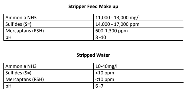
Stripper Feed Make up
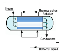 Reboiler: As mentioned previously, the steam, via the Reboiler supplies the drive for the Stripper tower. Direct steam injection or Reboilers can be used in this service. However, the advantage of using a reboiler is the condensate can be routed back to the Boiler house and be recycled. Thermosyphon Reboilers are commonly used in this service. Heat is gained from the tube side flow of the steam which in turn vaporizes some of the bottoms liquid creating tower drive. A steam to feed ratio is commonly used to regulate a proportional amount of reboiler steam flow in relation to the amount of incoming tower feed. The ratio controller produces a setpoint representing pounds of steam flow for each gallon of water to be stripped. If the steam to feed ratio was 1.5 to 1, this would mean 1.5 pounds of steam for each gallon of feed water.
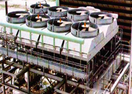 Pumparound cooler: The Stripper pumparound loop can have a water or air cooled condenser. The purpose of is to provide reflux to the tower and control the Overhead temperature. Because of high concentrations of NH3 and H2S, this equipment needs to be built with a higher grade metal.
Pumparound Pump: Takes suction from the Tower Chimney tray and routes reflux to the Pumparound cooler. The pump usually has an auto start spare and seal flushes.
Stripper Bottoms Pump: Takes suction from the Tower Feed/bottom exchangers and routes stripped water to a stripped water surge drum and/or desalter. This pump usually has an auto start spare and seal flushes.
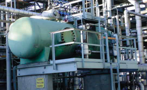 Stripped Water Surge Drum: Located downstream of the bottoms pumps, this Drum holds some surge capacity before it is routed outside the unit, usually crude desalters. It can also include an overflow to waste water. Instrumentation includes sight glasses, level controller and Low level alarms.
Operating a Safe, efficient unit
Safety: Good housekeeping in the unit is very important. Tools, hoses and ladders need to be in the proper location. PPE cabinets need to be stocked. H2S monitors and evacuation alarms need to be regularly tested.
Monitoring: Engineers and operators alike need to be vigilant as to any changes happening in the unit. This can be accomplished by visual verification and Sampling of both Sour Water Feed and Stripped Water be done on a shift by shift schedule, and more often if the process is upset, this would include checking pH. The Sour Water Storage Tank needs to be checked for level and oil pad verification. If there is a reasonable amount of oil, it should be skimmed off. The Sour water Flash drum oil side also needs to be checked routinely for oil side level. Unit Engineers need to be aware of Refinery volumetrics and any plant issues that might affect the storage capacity of the Tank.
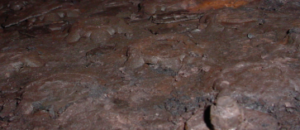
Better to keep your Tower looking like this:
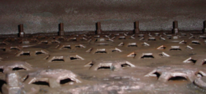
…Than this:
 Rolling Stock: Check pumps and drivers regularly for oil, vibration, seal leaks, hot motor bearings. If there is a seal flush with a strainer it needs to be blown through routinely. A Robust PMP (Preventative Maintenance Program) pays for itself. Fin Fans also need to be checked for vibration and proper lubrication.
Corrosion: Be aware as a Maintenance coordinator, Project lead, Inspector or Engineer, what your metallurgy issues are in a sour water unit. Keep your Inspection program current.
Environmental: Refiners need to adhere to Environmental regulations and understand Maximum Daily allowances for their facility. Units need to be designed to tolerate upsets so as not to flare and in the case of Sour Water Stripper bottoms a near normal pH if routed to Waste Water.
Stay tuned for Installment VI, which covers the Claus Unit!
____________________________
To read more in this series, visit our Blog.
For more on our Sulfur Recovery services, visit our Consulting page.


Leave a Reply
You must be logged in to post a comment.