


The Amine Unit Continued

Amine Unit
To better understand the relationship between Amine Processing, flow and equipment, we will “walk” through the unit. Every Amine unit will be set up uniquely, but it will have most of the same basic equipment. Let us begin:
Rich Amine to the Unit: Rich Amine is routed from the refinery absorbers to the unit typically from a common Header to a Flash drum.
Flash Drum: The purpose of the Flash drum is to do exactly that – flash off light hydrocarbon from the

Flash Drum
incoming Rich Amine. Typically there will be a pressure controller on the Drum that is set at approximately 15 psig and will open if the system is “Hit” from an upstream user. A “hit” could consist of a number of issues; foaming of the absorber, dirty Amine, high volume of return Amine. The list goes on. Heavier hydrocarbon will settle on the top of the Amine in the Drum. When the pad grows, it will spill over a weir and the Operators can pump the oil side of the drum to a slop tank, or blowdown system. Residence times in the Flash
Drum is approximately 20-30 minutes and usually includes a vortex breaker or stilling well. The drum is designed for Surge capacity to provide a consistent flow rate to the Regenerator. Instrumentation typical includes sight glasses for both Amine and oil side, High / Low level alarms.

Rich Amine Pump: The Rich pump takes suction off the Flash drum and is routed to the Feed/Bottom or Lean/Rich Exchangers. Because of the service, it is important the seals of the pump are robust usually including Dual mechanical seals. This can be a critical pump and usually has an auto start spare.
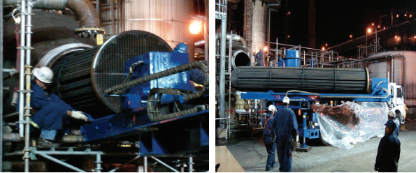
 Lean/Rich Exchangers: Rich Amine is routed through the Tube side of the exchangers and heated by the Lean Amine exiting the bottom of the Regenerator. The performance of this exchanger is critical to the process as a whole. Energy available from the lean amine stream is transferred to the rich amine prior to the Rich Amine entering the Regenerator. Care needs to be taken as to Temperature. Corrosion rates increase with increasing temperature, particularly in Rich Amine service. A temperature that is too high can result in the acid gas flashing and causing severe localized corrosion. The energy transfer between shell and tube side results in a decreased energy requirement for the Regenerator. Rich Amine runs approximately 220°F as it enters the Regenerator. The shell and tube (u-tube) exchanger are commonly used when a large amount of fluid needs to be heated or cooled. And they are used when bundles are pulled frequently for cleaning. Below are photos of an exchanger bundle being pulled by a bundle extractor for cleaning.
 Regenerator: The Regenerator is typically a trayed tower and includes 18 to 30 trays in the column, depending on the volume of Amine being circulated through the plant. The hot Rich Amine enters near the top of the regenerator. The trays provide liquid /vapor contact between the rising vapors and the descending liquid Amine. The rising vapors flow through the draw tray chimney moving towards the tower overhead. As hot, rising vapors encounter descending liquids; some water vapors condense while the H2S is released from the solution. A total draw tray is located below the first tray and collects Amine liquid that gravity feeds to a reboiler. Low pressure and high temperature favor amine regeneration. Typically a back pressure of approximately 15 psi is held by a Pressure Controller that feeds the Sulfur Plant downstream. The temperature of the tower is controlled by pressure. Regenerator Bottoms temperatures are approximately 255 ̊F @ 15Psi. Bottoms temperatures in excess of 255 ̊F greatly increase the rate of corrosion on piping. Instrumentation included for this tower are Flow, level, Pressure and Temperature indication both local and at control console. Sight glasses should be located on the tower for visual verification of level.
Reboiler: Several types of Reboilers can be used in the service such as Kettle or Thermosiphon. The purpose is  to heat the amine for stripping out the H2S gas, also known as clean or acid gas. In the case of a Kettle type reboiler, an internal weir holds back a liquid level that keeps reboiler tubes covered. Lean Amine spilling over the weir is piped to the regenerator tower bottoms level. Reboiler vapors, which include steam and H2S gas, are returned to the regenerator just below the draw tray. The Lean Amine loadings (grains per gallon H2S) are controlled by typically 50# steam to the Reboiler. Refineries using higher steam pressure would need a steam letdown station and desuperheater to better control the temperature. Steam rate is tied to the regenerator feed rate by the steam to feed ratio controller. The ratio controller increases steam according to feed increases. The ratio will be adjusted depending on regenerator bottoms sample results. If the grains/gallon H2S are high you would make a slight increase on the steam to feed controller. If the grains per gallon H2S are low you could make a small decrease on the steam to feed controller. Generally speaking, the ratio would fall between .8 to 1.0 pounds of steam per gallon of feed. The type of Amine will also affect this ratio. Plant Engineers commonly use process simulation software to optimize gas processing.
Overhead condenser: The Regenerator overhead condenser condenses vapors exiting the tower overhead. Cooling water flows through the tube side of the condenser lowering overhead temperatures from approx. 230°F to less than 100°F. The overhead condenser is one of the basic components, along with the Regenerator and the reboiler that represent the core operating blocks of the system. The condensed water returns back to the regenerator to control the overhead temperature, maintain Amine system balance and to knock down entrained Amine from vapors rising in the Regenerator.
 Reflux Drum: Condensed liquids from the overhead condenser are routed to the Reflux drum. The condensed water returns back to the regenerator. The acid gas is separated from the water by typically being routed through a demister pad. Vapor and droplets of liquid strike the demister. The velocity causes small droplets to coalesce with larger ones and drop out of the upward moving vapors. Ammonia and cyanide are soluble in Amine. Either of these compounds found in the sour gas will be scrubbed out and sent overhead. As the overhead condenses in the condenser the Ammonia is dissolved in the water, raising the pH. The high pH causes acidic cyanide and is absorbed in the reflux water. The Reflux drum is one of the pieces of equipment susceptible to corrosion. Instrumentation on the Reflux drum typically includes sight glasses for visual verification, Hi/low level alarms, along with level and temperature indication.
Reflux pump: The reflux pump, pumps the liquid, mostly condensate from the Reflux drum to the top tray of the regenerator. A portion of the pump discharge is sent to the Sour Water Unit.
The Lean Amine Surge Tank: The Amine system is a closed loop system, so the surge tank’s purpose allows for inventory change and to help the unit recover from foaming or flooding episodes. Pure amine or condensate can also be added to this tank to adjust the strength of the Amine being circulated to the Refinery. The temperature of the lean Tank should be set for approximately 10 -15° F warmer than Absorber gas temperatures (90-120°F) The strength is determined by what Amine is being used. Rinse water at refinery absorbers will tend to weaken Lean Amine strength. For this reason, water build-up is sloughed from the Regenerator Reflux drums to control Lean Amine tank level and consequently the Lean Amine strength. The tank itself usually has a gas or nitrogen blanket, as Amine exposed to oxygen can degrade over time. Steam coils might be needed depending on the climate to assure the solution viscosity does not increase in cold weather. Instrumentation for an Amine surge tank would include, Temperature and level indication (level being verified by gauging the tank) and pressure regulator for N2 or gas blanket.
Lean Pump: The lean pump is located downstream of the Lean/Rich exchangers and commonly takes suction off the surge tank. This is an important pump as it typically supplies the Refinery, so in most cases a spare pump is critical with an auto start. In some cases booster pumps are needed to assure needed circulation rate.
Reclamation
Reclamation is used to remove heat stable salts (HSS) from contaminated Amine. The Amine used will  determine how it will be reclaimed. Some Refiners have permanent Reclaimers installed in the unit, while other bring in outside Reclaiming companies and perform the work when the HSS threshold is reached. Reclamation can be done as a batch system or by routing a slipstream of the lean amine through the Reclaimer. A Reclaimer can be as simple as using a reboiler to boil the water overhead, leaving the HSS in the Reclaimer and disposing of it when it’s full or using an EDU (Electro dialysis Unit) which uses specific membranes and flow distribution spacers under an electric field to transfer specific ions from one solution to another, Amine and Caustic. Clean Amine is routed back to the unit and the Heat stable salts have dropped out in the waste stream.
Filtration
 Lean Amine filtration is designed to remove suspended solids, corrosion products or any foreign material present in the system. Filtration prevents contaminants from building up in the system. Failure to remove contaminants will ultimately result in lost efficiency by laying down on absorber trays and causing foaming. Common Filtration includes Particulate filter and Carbon. The particulate filter removes particulate materials from the Lean Amine stream. Filters used in this service are typically 5 to 25 micron, polypropylene, or cotton string wound. Although care must be taken in choosing the appropriate material, as it can promote foaming. The filter package may be full flow or a slip stream. Frequency of replacing filters represents how dirty the Amine system is and the microsize of the filter represents how much of the contaminants are captured. For example, using a 20 micron filter might be adequate but will not capture as much as a 10 micron filter. Where will the contaminants go that aren’t captured? They would settle on Absorber and Regenerator Trays. As “end of run” for the Amine unit nears, it is typical to experience more foaming and dp issues in your Regenerator and upstream Absorbers.
Lean Carbon Bed Filtration will remove a great number of organic and hydrocarbon contaminants in lean amine. Hydrocarbon causes foaming and impairs H2S absorption in the refinery absorbers. The Filter is not meant to remove HSS. It will function over a reasonably wide range of concentration, temperature, pressure and pH. Once a substance is absorbed in the activated carbon it will remain permanently in place unless physically or chemically removed. The most significant upsets that will degrade performance and shorten carbon life are large volumes of Hydrocarbon and use of Excessive antifoam chemicals. Anti-foam is used in the Regenerator and Refinery absorbers to “break” foaming that has occurred in the tower.
Post Carbon particulate filters are located downstream to keep carbon finds out of the lean amine system.
Rich filtration: Rich Filtration is located downstream of the Amine Flash Drum. It can be especially useful in times when Refinery Absorbers are upset. Caution should be taken when replacing filters because of the high levels of H2S.
Foaming: Foaming deserves a special section all to its own as it has wreaked havoc in many Absorbers and  Regenerators. Here is an example of foaming. Refiners have all sorts of different ways to remedy the issue including silicone and glycol based antifoam. The concern with using silicone based antifoam, is the Amine system becomes “addicted” to it for lack of a better word. It exhausts itself and no long performs. And the antifoam has to go somewhere and that would be the Carbon Filter. The Carbon Filter does an outstanding job pulling the antifoam out of the amine system. But it de-activates the Carbon shortening its’ life. To make things more confusing, foaming and the use of antifoam is not well understood. It has never been meant to be used on a frequent basis. Basic characteristics of foaming include: High Differential pressure on the tower as the foam layer builds, lower differential pressure when the foam level collapses along with increased level in overhead drum.

Operating a safe, efficient Unit
It takes a team effort by Engineering, Operations, Reliability, Safety and Environmental to successfully operate an efficient Amine unit. In 1993, The Amine Best Practices Group (ABPG) was formed by Industry leaders in the Oil and Gas sector. The information they gathered was from several companies and independent consultants. It is a great set of guidelines for operating an Amine unit.
Keep in mind the following:
- Safety: As basic as it sounds, good housekeeping in the unit is very important. Tools, hoses and ladders need to be in the proper location. PPE cabinets need to be stocked. H2S monitors and evacuation alarms need to be regularly tested.
- Monitoring: Engineers and operators alike need to be vigilant as to any changes happening in the unit. This can be accomplished by visual verification and Sampling of both Lean and Rich Amine, along with Regenerator reflux and bottoms. Making appropriate changes for Amine strength, keeping the system as clean as possible through filtration and making necessary adjustments on system temperatures will keep the unit in steady state.

Rolling Stock: Check pumps and drivers regularly for oil, vibration, seal leaks, hot motor bearings. A Robust PMP (Preventative Maintenance Program) pays for itself.
Corrosion: Be aware as a Maintenance coordinator, Project lead, Inspector or Engineer, what your metallurgy issues are in an amine unit. Key factors to keep in mind are; type of Amine and concentration, Amine loading, temperature, oxygen, inadequate design, too high flow rate. Some areas of the unit are more susceptible to corrosion such as; Reboiler, exchangers. Other areas are more susceptible to wet H2S cracking such as the top of the Regenerator and overheads.
Environmental: Refiners need to adhere to Environmental regulations and understand Maximum Daily allowances for their facility. Units need to be designed to tolerate upsets so as not to flare and operate in a way that follows the letter of the Law.
_________________________________________________
Stay tuned for Installment V of our Sulfur Recovery Series, where we talk about the sour water stripping unit. For more information about sulfur recovery and to learn about our consulting services, visit our Field Services Consulting page.
Leave a Reply
You must be logged in to post a comment.